

Hi, I'm Chris Butler , a senior in Computer Science here at Georgia Tech, and I'm Andrew Polkinghorne, a senior in Mechanical Engineering here at Tech.
Our project is a serial controlled card mover.
Insperation:
The idea behind this project is to eventually be able to sort large amounts of Magic The Gathering cards in a faster and more efficient method than a human.
Details:
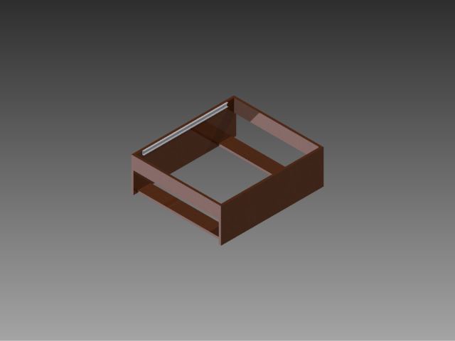
Physical System:
The design of our system is fairly simple. The first step is cutting the 4'x2'x6" Fiber board into the four 20"x3"x0.5" pieces and the two 8"x24"x0.5" pieces. These comprise the two walls and the support beams of the system. The four support beams should be attached with two horizontal against the ground and flush with the outside edge of the box, and two verticle mounted flush to the top of the structure. After putting the box together, the next step is adding the drawer rails to the inside of the box. To prep the rails before inserting them be sure to remove the wheels from the sides of all four rails so they may be used later. Also take note to flatten the notches in the rails where the wheels are intended to "lock" in place
The next, and one of the most important, steps is to create the inner gantry. To make the gantry cut the two 4"x1.5"x0.75" pieces and attach four the rollers to the outer 4"x.75" sides with two rollers on the same side of each piece. This is the part that will slide along the outer rails. Then on the .75"x1.5" side attach your last two drawer rails, connecting the two pieces. 
When putting the rail into the outer gantry it will become necessary to adjust for your specific system, but it is importat to have as little sway in the arms of your gantry as possible. After making the inner rails it is time to make the cart that will carry the fan. This is the 3.25"x0.5"x4" piece, with the 2.35"x2.75" hole cut through it. To the 4" sides of this attach the last four wheels vertically so the cart hangs below the rails. It is important to use the wheels with the rail curving to the wheel so that when the cart is attached to the rails it is constrained in the Z axis. With the cart in place it is time to add the printed parts. Project Files These files include all the pulleys and the shroud to extend the fan, as well as a mock up of most of the other parts in their expected configuration. The three shroud parts need to be glued together. Once glued together mount the rack gear in the slot in the fan duct. These parts should fit through the fourth printed part, which will fit into the hole in the sliding cart. The next step is attaching your actuators. The first actuator is the stepper motor placed under one side of the sliding rails. For this we used an angle bracket, it is important to give the stepper enough clearance on the back so that the angle bracket does not interfere with the axle. The bracket and motor should be mounted such that motor's axle is parallel to the side of the box. On the other side of the sliding rails, mount one of the sliding door rollers to act as the other side of our pully system. Again making sure that the axle is parallel to the side of the box.The 3D printed pully wheel should have a tight friction fit on the gear. Then attach two eyelets in line with the motor an pully to attach the speaker wire to. The tension on this wire can change the accuracy of the stepper by a great deal so be sure to test various tensions before setting it permantly in place. The next actuator is the servo controlling the up and down movement of the fan. For this we removed a section of the cart, just big enough to fit the mounting holes of our servo. Once we had the servo flush against the cart and the pinion gear attached to said servo making firm contact with the rack, we super glued it in place. The final actuator is the servo moving the sliding rails. The steps for this are exactly the same as those of the cart. first attach the servo so that its axle is perpendicular to the movement of the sliding rails. Placement of this needs to be just past where the rails attached to the box end, and slightly below them. Then get a circular gear plate for the servo and super glue the 3D printed pully wheel in the center of it. In line with this pully, mount another door wheel. On the closest side of the sliding rack affix two eyelets to connect the wire to. Much like the one on the stepper getting the tension on this wire just right is also important. Once the tension is figured out crimp the ends of the wires back onto themselves using the wire fasteners. The final step is mounting the limit switches. You should mount one switch on the X rail at the starting position, and one on the Y rail at the starting position. Then mount one switch inside of the fan duct so that it will be tripped whenever it touches a card, and one on the outside of the duct for whenever the duct reaches the maximium desired height. With this the actual system is complete. All that is left is creating the bins to sort the cards into. For this it is advised to make them in whatever tolerance the system is capable of. To ensure it would work, we ran the system to each position then traced where the fan duct touched the ground and made our bins around those tracings.
Circutry:
Our circutry consists of the four switches and pull down resistors, four MOSFETs to control the stepper motor, one relay to control the fan, and the Teensy microcontroller to control everything. Here is an image of our circut diagram.

Code:
Due to time limitations, our initial goal of having the system sort the cards became infeasible. Because of this, we focused our efforts on creating a system that could be easily manipulated via serial input. To this end We designed all of our microcontroller code to work off of three python commands that can be run either through the python idle or through a command prompt after starting python. The most important being to import the serial library. [ import serial] Next is connecting to the appropriate port on the teensy. [ser=serial.Serial('/dev/ttyACM0',9600)] In this command replace the [/dev/ttyACM0] with whatever port the teensy is currently attached to. The last step is to simply write the number of the bin you wish to collect a card from to the serial buffer. [ser.write('B')] The bins in our case are numbered from 0-B in hex. Here is a link to our microcontroller code.
Chris & Andrew SCRUM
More Pictures of the project
Dimensions:
4x 20"x3"x0.5" Medium Density Fiberboard Handy Panel
2x 8"x24"x0.5" Medium Density Fiberboard Handy Panel
2x 4"x1.5"x0.75" Pine Wood
1x 3.25"x0.5"x4" Medium Density Fiberboard Handy Panel (2.35"x2.75" hole cut through)
Liberty 22 in. Self-Closing Drawer Slide (wheels removed)
Circuit box made from 12"x24"x3mm Craft Plywood size 2.5"x2.5"x7" (holes cut to fit wires)
Card bin base 5mmx16.25"x20.125"
Card bins 1.5" tall by 2.8"x3.9"
Overall size 24"x21"x13.5" excluding cables
Parts List:
250 Ft Power Wire Red Audio Electronics Speaker Power Wire (Audiopipe Pw4rd) Lab
sliding screen door tension roller B-522 pulleys x2 (B-522) $5.47 ea The Home Depot
SpringRC SM-S4303R Continuous Rotation Servo x2 $12.95 ea Pololu (Lab)
Touch sensors/pushbuttons x4 $9.99 EBAY
Loctite 20g Professional Liquid Super Glue Model# 1365882 $5.97 Homedepot
9880WK Breadboard-Prototype Design Aid $9.25 Elenco
MOSFETS IRF-630 x4 $1.39ea Ebay
COTO 9007-05-01 Series Spartan SIP Reed Relay $1.22 Digikey
JMC/DATECH DS9238-12HBTL 92mm Case Fan w/ Thermal Sensor (discontinued) DATECH
JT&T Expandable Sleeving Clean Cut PET ID: .5" (4110F) $10.96 Fry's Electronics
THOMAS BETTS RC737 3/8 IN TERMINAL WIRE BOAT PRESSURE CONNECTORS (SET OF 20) $17.95 Ebay
Already Purchased:
Teensy Microcontroller
Webcam (light)
Laptop
Stepper Motor Brother BP484223LM38 (Price unknown obsolete part) Brother
1/2inx2ftx4ft Medium Density Fiberboard Handy Panel Model# 1508108 $9.73 Homedepot
3/16 in. x 48 in. x 96 in. Tempered Hard Board Model# 832780 $13.25 Homedepot
Liberty 22 in. Self-Closing Drawer Slide (Model#D68822C-W-TS) x2 $7.48 Home Depot
Electrical Tape
12"x24"x3mm Craft Plywood midwestproducts
Assorted Connector wires
RDI pushbutton unknown model (Normally Closed) x4
1Kohm Resistor x4
1 rack and pinion gear set from HP LaserJet 21007N
3D printed pulleys x2
3D printed fan box
3D printed duct
8volt AC power adapter MODE
9volt AC power adapter Anoma Electic Co.
Angle bracket

Problems Encountered
Stepper motor (reason too much friction in rails motor unable to compensate due to weight)
Computer vision (insufficient time to complete)
Design mistake in duct support (missing slot for rack)
inner gantry cart too small (snapped in half when trying to make hole for duct support, larger cart built)
suction cup design (suitable vacuum device could not be acquired)
MOSFET control of fan not possible (relay used instead)
Fan and stepper could not be run off of same power supply (likely due to insufficient current)