|
|
|
|
PrudFX camera motion matchingDigital Video Special EffectsCS4480 Spring 2000 Jason Craig
our movie:
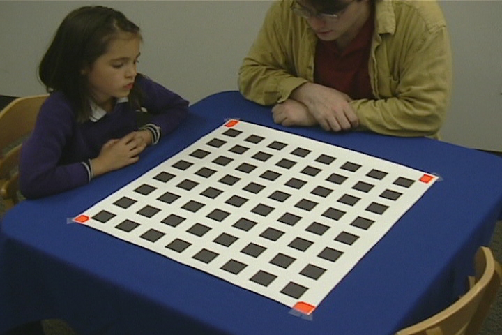
This document describes the lengthy process of taking real world camera footage, determining the intrinsic and extrinsic parameters for the camera, and feeding these to the animation program in order to create a model camera which matches the real world camera. This is suggested for folks who have lots of processing power, lots of time, and lots of disk space. Also, make sure that during the filming and taking shots of reference frames, that you do not adjust any of the internal parameters of the camera (i.e., make sure that all the auto stuff is off, don't zoom, and don't change the focus). The code could be changed to account for changing these things, but our code does not handle such cases. Setting upThe calibration pattern should be printed out and it should be verified that it is symmetric. Also, you should take footage of the calibration pattern from 4 or 5 different angles (see note about reference frames below)..pdf file of the pattern calibration_pattern Raw footageIn order to use this pipeline, the raw footage must contain the camera calibration pattern (large enough in the frame so that each square is distinct). The pattern should include some brightly colored markers at each corner so that the videomunger program can find them. We used orange gaff tape and it worked like a champ in ideal lighting conditions (like by a window). The first step in the pipeline is to take the raw footage (in the form of an uncompressed .avi) and feed it through the videomunger program. The outputs from the videomunger program will be all of the frames (as bitmaps), a file called bounds.txt, and a file containing the number of frames that were processed. Ultimately, the bounds file that gets passed into the LocateSquares program needs to be formatted so that the number of frames is the first line, and the subsequent lines represent the 4 corners. This can be done easily by concatenating the bounds.txt file and the numframes.txt file. The frames and the bounds file describing them must then be pumped through a Java program which will determine the corners of each individual square in the pattern based.Videomunger.tar
Java program LocateSquaresThe Java program takes as input a file which describes the setup. This file is pretty self-explanatory. One thing about the Java program is that it takes uncompressed .tga files. However, the output of the videomunger program is .bmp files. Thus, you will need to batch-convert the .bmp files to .tga files. We used a program we found on the web called gbmref. It is a Windows executable and the syntax we used to convert the files was "gmbref file.bmp file.tga". Once the .bmps are converted, to execute the Java program, you will need to set up the CLASSPATH variable to include./Java:./Java/numerical:./Java/dots Once this is setup, you can run the program by typing "java LocateSquares calibscript.txt" Hours and hours later you should have a points##.txt, and marked##.tga file for each frame. You should check the marked##.tga files to make sure they look reasonable. The important stuff here are the points.txt files. calibscript.txt
EasyCalibOnce you have all the points##.txt files (one for each frame), you can use the EasyCalib program to get out the extrinsic and intrinsic camera parameters. There is documentation on what these parameters mean in Zhengyou Zhang's paper. The EasyCalib program requires a file that describes the model (the calibration pattern), and a points##.txt file for each frame. Unfortunately, EasyCalib is very memory intensive and trying to do >=30 frames at a time is not advised. What we did was to take 4 or 5 still shots of the calibration pattern from very different angles (this is IMPORTANT: make sure you read about the specific cases that are excluded in ZZ's paper or you may need to repeat a lot of work). Then, we used the BoundTracker program to determine the corners of the model file for these reference frames (this is the same thing that our videomunger code does, only you have to do it by hand here). BoundTracker will produce a bounds file representing the reference frames. We then ran this data through the LocateSquares program just as we did with our real frames. Next, we compared each of our real frames to the reference frames to extract out the parameters for that frame. We used a batch file to run EasyCalib on each frame. This was a great speedup since if we tried to do all 900 frames at once, we would still be waiting for it to complete. Since EasyCalib's output will also include data for the reference frames, these need to be chopped out and all the individual files need to be merged into one (in order of course). There is a Java program to munge all these files together. To execute it, just run "java Munge" on the files created from the EasyCalib batch file below.model file generator, GenModel.exe (be careful
with this one)
Note that ecresults.txt looks like output straight from EasyCalib. Getting data into Maya2.5Now that we have a file that describes the camera for each frame, we created a virtual camera in Maya2.5 by using Paul Bennett's cameraPath plug-in. This plug-in takes in a file with essentially the data that you get from EasyCalib. To go from EasyCalib output to the form that the plug-in understands, we have a Java program called ECtoMaya (EasyCalib to Maya). To use it, just run it on the output from Munge above, i.e., "java ECtoMaya ecresults.txt". This should produce a file called ectomaya.out which can be read into Maya using the cameraPath plug-in. We also ran a smoothing algorithm on the output of ECtoMaya because the data was pretty noisy. The Graph Editor in Maya is also a helpful tool to eliminate sharp spikes that may be harmful to your camera path. The details of this step are: 1. Load Maya2.5 (use the best machine you can
find)
Now there should be a camera called "cameraName" which should have the appropriate fields set for each frame. Just pair this with an animation, and render it as a .tif sequence or some other format that can be imported into After Effects. We used the command line renderer (try 'Render -h' on an SGI to get the options). Don't forget to do something in After Effects to remove the calibration pattern (note: you should think a lot about this step early on). EasyCalib to Maya Java program ECtoMaya.tar
Questions:
|
|
|
© 1999-2007,
College of Computing, Georgia Institute of Technology, All rights reserved. |