
|
|
CS 2200 Intro to Systems and Networks
|
This document describes the LC-2200-32 processor enhanced with interrupt support instructions, and the FSM for its implementation. This manual assumes you have familiarity with the LC-2200 datapath.
The LC-2200-32 is a 32-bit computer with 16 general registers plus a
separate program counter (PC) register.  All addresses are word addresses.
Register 0 is wired to zero: it always reads as zero and writes to it
are ignored.

-----------------------------------------------------------------
                          Instruction Formats
-----------------------------------------------------------------
There are five instruction formats.  Bit 0 is the least-significant:

R-type instructions (add,nand):
 bits 31-28: opcode
 bits 27-24: reg A
 bits 23-20: reg B
 bits 19-4:  unused (should be all 0s)
 bits 3-0:   reg DST

I-type instructions (addi, lw, sw, beq):
 bits 31-28: opcode
 bits 27-24: reg A
 bits 23-20: reg B
 bits 19-0:  OFFSET (a 20-bit, 2s complement number with a range
                     of -524288 to +524287

J-type instructions (jalr):
 bits 31-28: opcode
 bits 27-24: reg A
 bits 23-20: reg B
 bits 19-0:  unused (should be all 0s)

O-type instructions (halt, ei, di, reti):
 bits 31-28: opcode
 bits 27-0:  unused (should be all 0s)

-----------------------------------------------------------------
                         Register Convention
-----------------------------------------------------------------
Registers indicated with a '$' sign.  The register names in assembly
are according to their use in the assembly convention:

regno   name                      use                  callee-save
-----   ----            -------------------------      -----------
  0     $zero           always zero (by hardware)         n.a.
  1     $at             reserved for assembler            n.a.
  2     $v0             return value                      no
  3     $a0             argument or temporary             no
  4     $a1             argument or temporary             no
  5     $a2             argument or temporary             no
  6     $a3             argument or temporary             no
  7     $a4             argument or temporary             no
  8     $s0             saved register                    YES
  9     $s1             saved register                    YES
 10     $s2             saved register                    YES
 11     $s3             saved register                    YES
 12     $k0             reserved for OS/traps             n.a.
 13     $sp             stack pointer                     YES
 14     $fp             frame pointer                     YES
 15     $ra             return address                    YES

-----------------------------------------------------------------
                    Instruction Semantics
-----------------------------------------------------------------
Assembly language       Opcode in binary      Action
name for instruction    (bits 31/30/29/28)
-----------------------------------------------------------------
add (R-type format)       0000      add contents of A with
  ex: add $v0, $a0, $a1             contents of B, store results in
                                    DST.  Ex: $v0 := $a0 + $a1

nand (R-type format)      0001      nand contents of A with
  ex: nand $v0, $a0, $a1            contents of B, store results in
                                    DST.  Ex: $v0 := ~($a0 + $a1)

addi (I-type format)      0010      Add OFFSET to the contents of A
  ex: addi $v0, $a0, 25             and store the result in B.
                                    Ex:  $v0 := $a0 + 25

lw (I-type format)        0011      load B from memory.  The memory
  ex: lw $v0, 0x42($fp)             address is formed by adding
                                    OFFSET to the contents of A.
                                    Ex: $v0 := memory[$fp + 0x42]

sw (I-type format)        0100      store B into memory. The memory
  ex: sw $a0, 0x42($fp)             address is formed by adding
                                    OFFSET to the contents of A.
                                    Ex: memory[$fp + 0x42] := $a0

beq (I-type format)       0101      compare the contents of A and B.
  ex: beq $a0, $a1, done            If they are the same, then
                                    branch to the address
                                    PC+1+OFFSET, where PC is the
                                    address of the beq instruction.
                                    Ex: if ($a0 == $a1)
                                           PC := (PC+1)+OFFSET

                                            *** NOTE ***

                                    For programmer convenience (and
                                    implementor confusion), the
                                    assembler *computes* the OFFSET
                                    value from the number or symbol
                                    given in the instruction and the
                                    assemblers idea of the PC.  In the
                                    example, the assembler stores
                                    done-(PC+1) in OFFSET so that
                                    the machine will branch to label
                                    "done" at run time.

jalr (J-type format)      0110      First store PC+1 into B,
  ex: jalr $at, $ra                 where PC is the address of the
                                    jalr instruction.  Then branch to
                                    the address now contained in A.
                                    Note that if A is the same as B,
                                    the processor will first store
                                    PC+1 into that register, then end
                                    up branching to PC+1.
                                    Ex: $ra := PC+1; PC := $a0

halt (O-type format)      0111      halt the machine:  i.e. do nothing
  ex: halt                          and let the simulator notice that
                                    the machine halted.

ei (O-type format)        1010      enable interrupts
  ex: ei

di (O-type format)        1011      disable interrupts
  ex: di

reti (O-type format)      1100      return from interrupt by loading address
  ex: reti                          stored in $k0 into the PC and then
                                    enabling interrupts

----Assembler Directives----

noop (pseudo-op)          n.a.      No operation: does nothing (actually
  ex: noop                          Emits "add $zero, $zero, $zero")

.word (pseudo-op)         n.a.      fill word with a value.
  ex: .word  32                     Ex: fill the current location
                                    with the 32-bit represenation of
                                    the number "32".
The following is a diagram of the LC-2200-32 datapath.
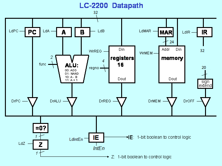
The meaning of each signal is defined in the FSM ROM section below.
A description of each datapath component follows.
Some items mentioned in this section are not implemented yet. The implementation is part of your assignment for this project.
For the purposes of this assignment, we have chosen to keep the interrupt vector table to be located at address 0x00000000 and has a length of 16. Program memory starts at 0x00000010.
The hardware timer will fire every so often. You should configure it as device 0; it should place the assigned index (its driver is located on the vector table) onto the bus when it receives an IntAck signal from the processor.
Go back to the main project page.